Electrical wiring is defined as the installation of cabling, associated with devices like switches, distribution boards sockets and light fittings in a structure. But to truly understand electrical wiring, we have to dig a little deeper than that. There are different types and methods of wiring, as well as safety precautions, that must followed and various electrical parts that are involved in the process that you should familiarize yourself with. Read on for a very in-depth look at what is involved in the electrical wiring process and what you need to know when working with the wiring in your home.
Methods of Electrical Wiring
There are different methods of electrical wiring which include joint box or joining system and loop-in or looping  system. The method you choose should be determined by the application you are using the wiring for, your budget, convenience and more. We will explain more about these methods here:
Joint Box or Joining System: In this type of wiring, connections to appliances are made through joints. The joints are made in joint or junction boxes. Suitable connectors or joint cutout are used to connect the wiring. The first step in this type of installation is to remove the insulation from the wire. There are several different types of joints that can be used to connect these cables, and sometimes, you can simply wrap or knot them together. The method you use in your joining system may vary according to the voltage, type of cable, joint, connector, application and other factors.
Some may think that the joint box system is a good method for electrical wiring because it doesn’t use a lot of cables, and is, therefore, less expensive than other methods. However, buying joint boxes will be an added expense which can make up for the fact that you are saving on wiring.
Though expenses may or may not come into play, if you use a reliable joint to connect your wiring, then the result should be a safe and dependable connection for a wide range of applications and voltages. It is a relatively simple way to create a wiring connection, whether temporary or permanent.
Loop-In or Looping System: The looping system is another method that is often used in wiring. Commonly used for lamps and other appliances, a wiring is connected in parallel so each appliance can be controlled individually.
When a connection is needed at a light or switch, the feed conductor is looped in by bringing it directly to the terminal and then carrying it forward again to the next point of feed. The switch and light feeds are carried around the circuit in a series of loops until the last circuit is reached. Phase or line conductors are looped in at the switchboard or box while neutrals can be looped either in the switchboard or from the light or fan.
There are both advantages and disadvantages to the loop-in system. Some advantages include the fact that it doesn’t require a joint box, allowing you to save money. Also, there are no joints which may have to be concealed between floors and roof spaces. Another advantage is that the fault location is accessible since the points are made only at the outlets.
As far as disadvantages, loop-in wiring requires more cables which makes voltage drop and copper losses more likely. It can also be difficult to perform in applications involving switches and lamp holders.
Types of Electrical Wiring
 Just as there are different methods of electrical wiring, there are also different types. These include cleat wiring, casing and capping wiring, batten wiring, lead sheathed wiring and conduit wiring. The wiring you use will vary according to the application it is being used for.
Cleat Wiring: This is a system of wiring which uses ordinary VIR or PVC insulated wiring (occasionally sheathed and weatherproof cable) that is braided and compounded and held on walls or ceilings with porcelain, wooden or plastic cleats. It is used for temporary wiring so it is not suitable for residences, although it is occasionally found in older structures.
Cleat Wiring has its advantages and disadvantages. Some advantages include the fact that it is a simple and cheap type of electrical wiring. Also, because it is often used in open air applications, the system is easy to access for repairs and inspections. Installation is relatively simple and customization can be performed easily as well.
For the disadvantages, these are visible, thus, it can be unattractive.It is also not recommended for permanent use due to the fact that the wiring can possibly sag. It is exposed to steam, humidity, smoked, rain and chemicals, which could later on damage the wires and cables, resulting in accidents in the long run.
Casing and Capping Wiring: In this system, cables are run through a wooden enclosure that has grooves. These grooves serve to hold the cables in place. The casings that hold the wires are usually attached to the wall or ceiling with screws. Once all of the cables are in position, a cap is put on top of the casing to cover the wires. This type of wiring is also no longer used in permanent, modern construction, but can be seen in some temporary applications.
Some advantages of casing and capping wiring include the fact that it is inexpensive, strong and longlasting. It is easy to customize and repair, as long as the phase and neutral wires are installed in separate slots. It is protected from the weather and elements due to strong insulation in the casing and capping, which also helps reduce the risk of electric shock.
On the downside, this system is at high risk for fire and doesn’t last well in conditions where acidity or humidity is high. It is also expensive to repair, requiring costly materials that can not be found easily. Termites have also been known to cause damage to the casing and capping of the wood.
Batten Wiring: This is a system that runs insulated cables through wooden battens that are fixed to walls and ceiling with plugs and screws. Brass clips are used to fit cables on the battens which are attached using nails that are resistant to rust. Batten wiring is often used for indoor installations.
Batten wiring is simple and easy to install. It is relatively inexpensive and attractive to the eye. It is strong, longlasting and easy to repair or customize. It is also resistant to leaking.
Unfortunately, batten wiring can be problematic because of its sensitivity to humidity and chemicals. Wires are visible, therefore, these are susceptible to heat, dust, steam and smoke. This type of wiring also does not work well with heavy wires and is only suitable for voltages below 250. It also requires a lot of cables and wires for installation.
Lead Sheathed Wire: This type of wiring uses conductors that are insulated with VIR and covered with a coating of an aluminum lead alloy. This works to protect the cables from corrosion and other damages. Wooden battens run the wires and are fixed with clips.
Lead sheathed wiring can serve as a protection against hydrocarbons and moisture. They offer excellent corrosion resistance and come in handy for earthing or grounding applications.
However, lead is both a heavy and soft metal. Because it is heavy, it makes it difficult to work with and costly to install. There are also environmental concerns being that lead can be harmful and is even forbidden in some countries.
Conduit Wiring: Conduit wiring can be either surface or concealed wiring. This system uses PVC cables that are run through conduit pipes constructed of PVC or steel. If the pipes are visible on walls or ceilings, it is considered surface conduit wiring. If the pipes are located on the surface or ceiling the wiring would be referred to as concealed.
The PVC in conduit wiring is highly resistant to corrosion. The system is very durable and popular as well as being waterproof. There is no risk of electric shock. It is easy to maintain and customize.
On the downside, conduit wiring is difficult to install, this, it is more labor intensive and costlier. The fault finding process can be also be challenging. Additionally, steel conduit, can be very expensive if it is used in this system.
The Importance of an Electrical Wiring Diagram
 An electrical diagram is very important in the wiring process. There are many advantages to drawing up a diagram before starting your electrical project. First is for an effective project management.. The diagram will tell you the key areas that may be problematic including sharp corners, tight walls and potential wet spots. Being able to anticipate problem areas can help you plan ahead so they can get through these areas quickly.
Electrical wiring diagrams also save time and money. This is because they can help you plan exactly what type of wiring will work best for your property. It can also give you an idea how much wire will be needed to complete the construction. That means you won’t end up wasting wire or have to stop what you are doing to run out for more. All of these occurrences could drive up the cost of the project.
Another advantage to an electrical wiring diagram is it prevents injury. Working with electricity can be extremely dangerous and a diagram can help electricians anticipate areas where injury is likely. These could include spaces that have nails or sharp objects or where a potential shock can occur. Obviously, injuries can lead to hospital trips, increased medical expenses, emotional trauma, or worse, death.
Electrical Wiring Colors
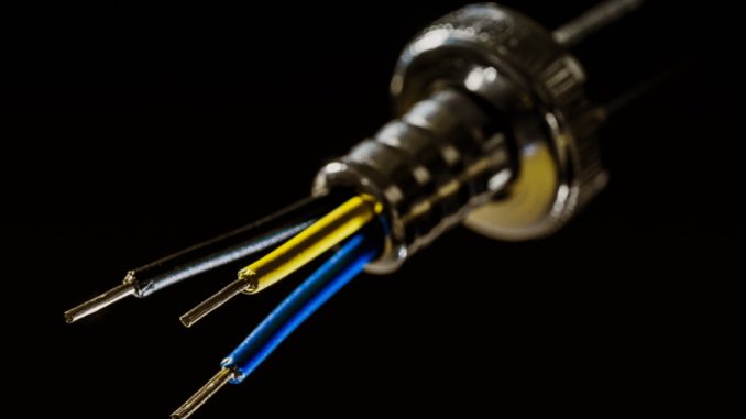
Electrical wires come in different color and each has its own purpose. The colors will indicate the type, size and function. Some may think that the different colors of wire are not important and that they should all work for installation. However, this is not the case. Using the wrong color can be dangerous as you are not following its purpose. When you have used the right color and in case a problem occurs, you will have an immediate idea which one should you replace to fix the problem.
Red: These are used for hot wires, switch legs and are the second hot wire used in 220-volt installations. They can also be used to interconnect wire between two hardwired smoke detectors.
Green: Green and bare copper wires are used for grounding only. These will ground devices and are bonded to junction boxes and appliance connections for safety.
Yellow and Blue: These are used as hot wires. They’re usually pulled in conduit. Blue wires are often used for travelers in three- and four-way switch applications. They can also be used as switch legs to control things like lights, fans and switched outlets.
White and Gray: These wires do not follow general rules. They may be used for the second hot wire on a 240-volt appliance or outlet connection. They can also be used as a switch leg for lighting or for running a three-way switch application. Because it is not easy to tell what these wires are being used for, it is a good idea to mark them to show that they are being used for something other than a neutral. To do this, you can simply mark the end of the wire with black or red electrical tape to avoid confusion.
Black: These are always used for hot wires. They may feed a switch or outlet and are often used for switchblades. It is important to never use these wires for neutral or ground connections.
Electrical wiring can be very dangerous and the more you know about it, the better. It is important to understand the different types and colors of wires, as well as the various methods used in wiring. It’s also key to create an electrical wiring diagram before beginning on your project. Keeping all these in mind, you can look forward to a safe and efficient electrical wiring experience when you visit a reputable USESI branch for your project needs.

